

Can You Use A Photoresistor To Sense Color?
six.1 Objective of the Colour Lab
The purpose of this lab is to introduce basic experimental concepts of gathering sensor data that is involved with hardware. You volition obtain information and utilize it to modify the output of the program. You will also become an introduction (or a refresher) on colour and how nosotros and how machines tin can percieve color and lite. While we can identity colours easily, machines do non.We will further practice reading and writing more complicated pieces of code. As before you lot will exist given code merely this time it will take some jumping around in the program to fully understand what is happening. We volition also introduce new ways to debug code past accessing the values of your variables by printing them to a Serial Monitor.
The outcomes of this lab are:
- Use the serial monitor to obtain data from an Arduino programme.
- Write procedures that take parameters and return a result.
- Use pulse wave modulation to control the intensity of a LED.
- Get more practice at analog input.
- Get more practice at complicated logical sequences of if-then statements, particularly in situations where the decisions are fuzzy and crave thresholds.
- Apply the absolute value office.
- Accept into account that physical devices need to be calibrated to take into account that both the devices and the physical earth they interact with are non necessarily abiding or consequent over fourth dimension.
vi.2 Background Information: Color and Light
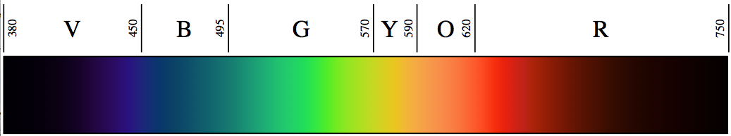
Humans perceive colour by how their red, green, and blue cones reply to the light coming from the environment. We have a circuitous visual organisation that takes into account the light illuminating the surface equally well equally the light from the surface. The visible light spectrum refers to the style our visual system translates light wavelengths into primary colors. See below for the typical human relationship between wavelength and color.Machines practise non perceive color, the best they can do is sense the mix of wavelengths arriving on their sensors and translate it to what a human might name as a colour. Color cameras have three sensors that filter the light into red, greenish, and blueish intensities and utilize this to record color. Cameras also have a white rest which is used to estimate the kind of light that is falling on the scene.
6.3 Materials and Tools
Photoresistor| The Arduino does not have a camera, simply it does have a elementary light sensor called a photoresistor. Information technology is a device whose resistance varies with the intensity of the light falling on it. Equally the light gets stronger the resistance decreases. Thus you tin can mensurate the amount of light falling on the photoresistor. If you arrange the photoresistor in a voltage divider circuit, so you tin mensurate a voltage that is proportional to the resistance of the photoresistor, and thus is proportional to the intensity of the light. When the illumination on a surface is of a particular colour, then the photoresistor tin can exist used to sense how well that color is reflected or absorbed by the surface. By measuring the amount of red, dark-green, and blue being relfected from the surface we tin detect the colour of the surface. | 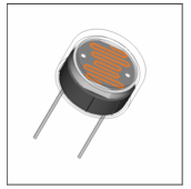 |
Hither is a more than detailed article on this http://www.sentex.ca/~mec1995/tutorial/photocell/photocell.html.
Multicolour LED
Nosotros can create almost whatsoever color by mixing red, green, and blue lite. A RGB LED has three LEDs inside one package. By varying the intensity of each LED you can mix these main colors and generate a wide range of colour hue (the actual mix of colors) and saturation (the amount of white mixed in with the color).
The intensity of a LED is controlled past turning it off and on very chop-chop. Your middle cannot see the flashes, just it can detect the proportion of on and off time. The more than on the LED is, the brighter it appears to you. This on-off timing relationship is called a duty bike. Duty wheel describes the proportion of ane unit of measurement of time during which the device is on. So a 100% duty wheel means e'er on, 50% means on one-half the time, and 0% means off. Yous can operate a digital output in Pulse Width Modulation (PWM) fashion past using the analogOutput function. Y'all give the function a digital pivot number and a duty cycle value (from 0 to 255) where 0 is 0% (LOW) and 255 is 100% (Loftier).
The Serial Monitor
And so far we have not had to become complicated data out of the plan running on the Arduino. But now nosotros need to get the actual intensity measurements for the colors we sense from the surfaces. Once you have uploaded the program, select the serial monitor (Tools -> Serial Monitor or look for a manifying drinking glass symbol), and you should get a window that will showtime press the measurement results in a form something similar this:
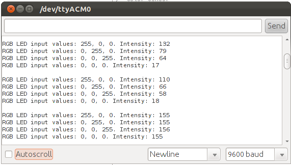
In this example, a red sheet of paper is held over the sensor and then removed. 110 is the intensity of the red reflected back when a scarlet piece of newspaper is held over the multicolour LED. The 66 and the 58 evidence the intensity of the light-green and blue being reflected to the photoresistor from the scarlet sheet of paper.
The image as well demonstrates that you should not use the first readings when yous hold a coloured piece of paper overtop because you may read the values from when you lot did non take the sheet of paper overtop. It would be best to not read the showtime set up of values when you hold the paper over the photoresistor.
half-dozen.4 The Circuit and Code
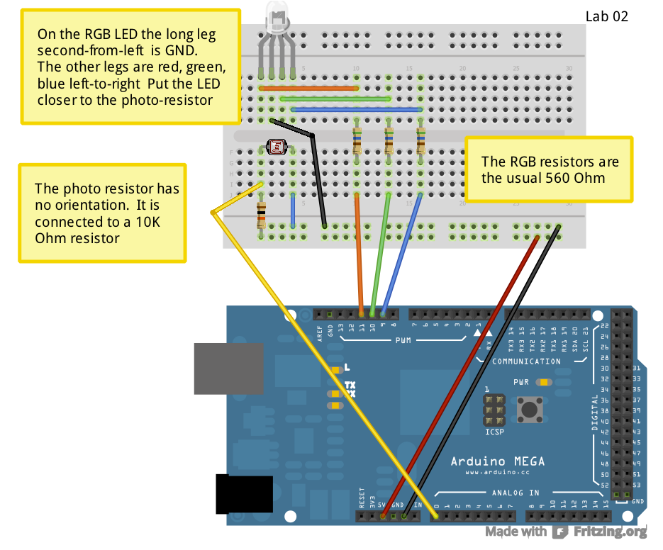
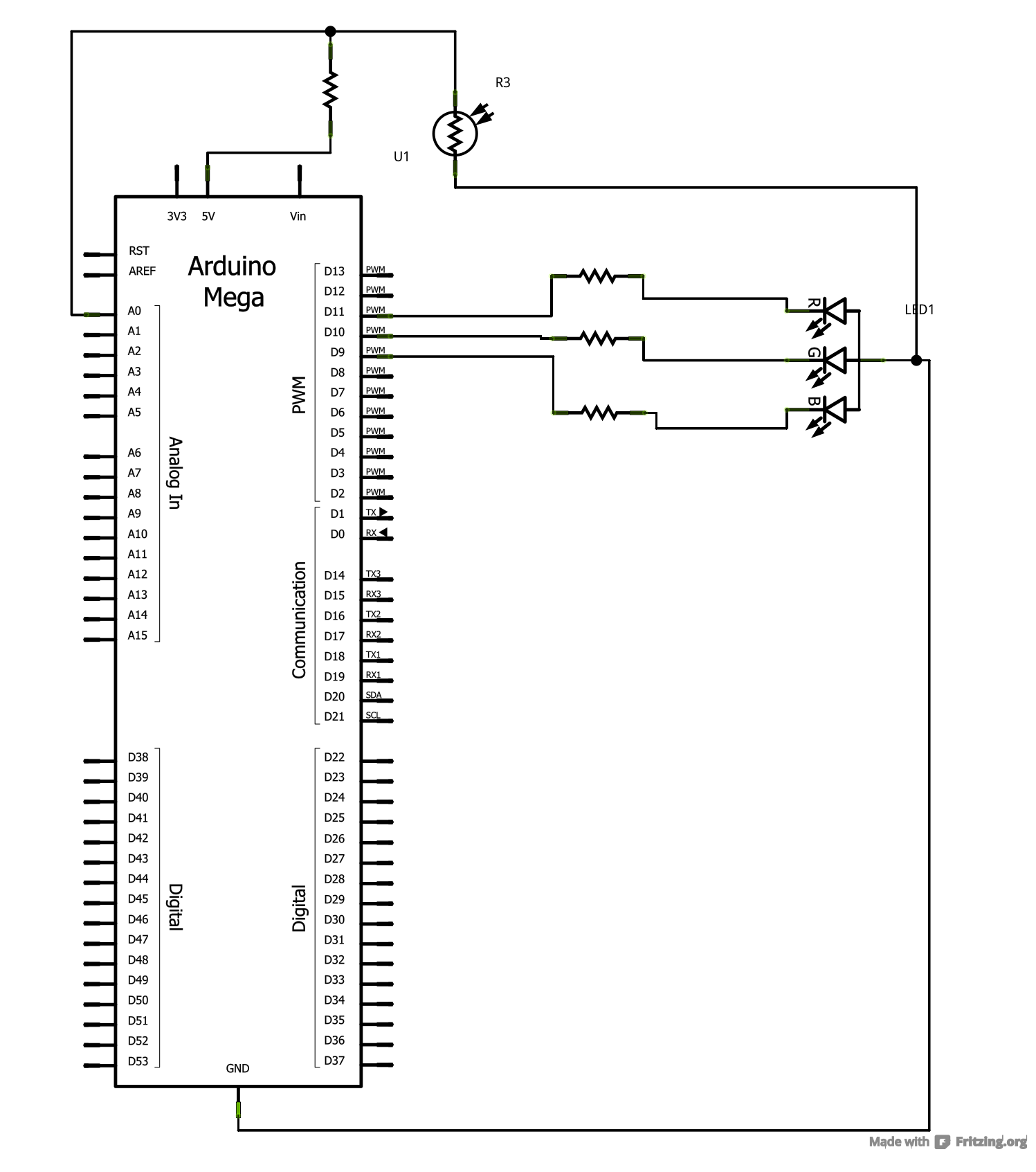
Become ahead and build the circuit below and load the program. Annotation how there is a blackness paper collar effectually the photoresistor. This is to shield it from stray low-cal so that information technology only sees what is above information technology. If you have the black box version of the kit, then yous can go a dark environment by putting the Arduino in the box and partially closing the chapeau. Note: The longest LED pb on the RGB LED is the Footing. The other paths of the leads must each take a 560Ω (Green Bluish Brown) resistor! Hither is more of import wiring information about the RGB-LED!For the Photoresistor, it does not matter which style you lot hook up the wires, just as long as there is a 10kΩ (Chocolate-brown Blackness Orange) resistor in the positive path. If y'all don't have a 10kΩ resistor handy, and then you tin can use the 10kΩ potentiometer: it has a 10kΩ resistance betwixt the end pins. If you want to get clever, y'all tin can use the potentiometer to calibrate your sensor by hooking information technology up as a variable resistor: apply ane end and ane centre pivot.
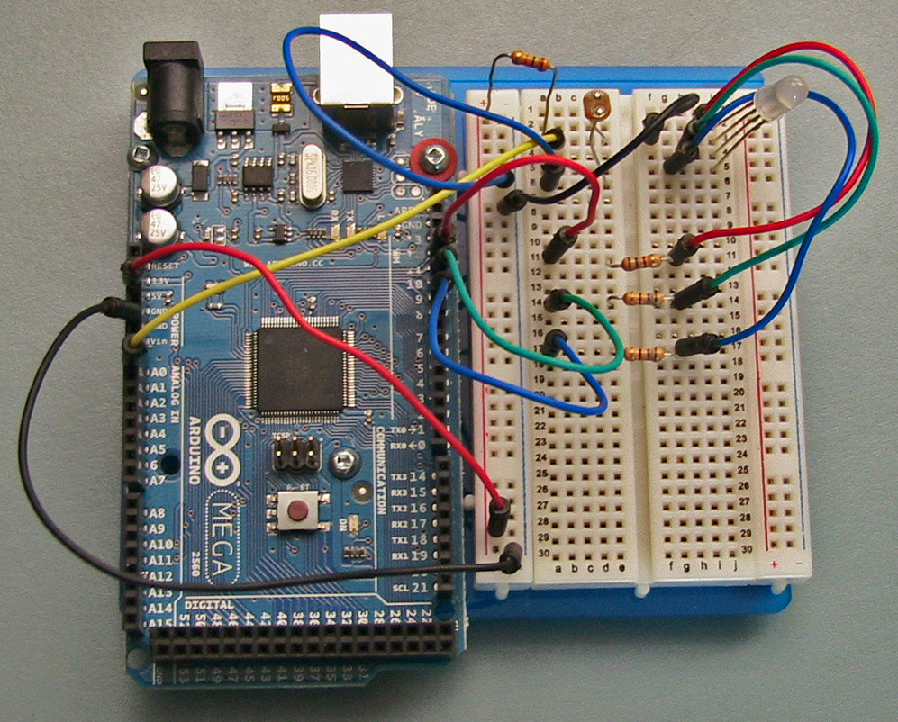 | 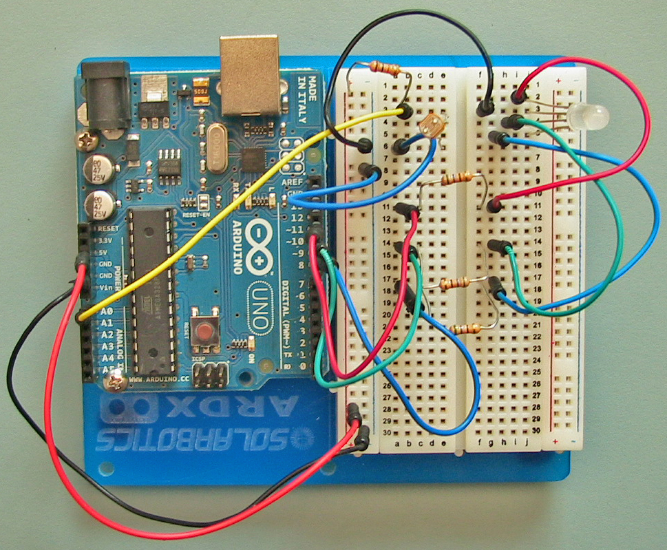 | 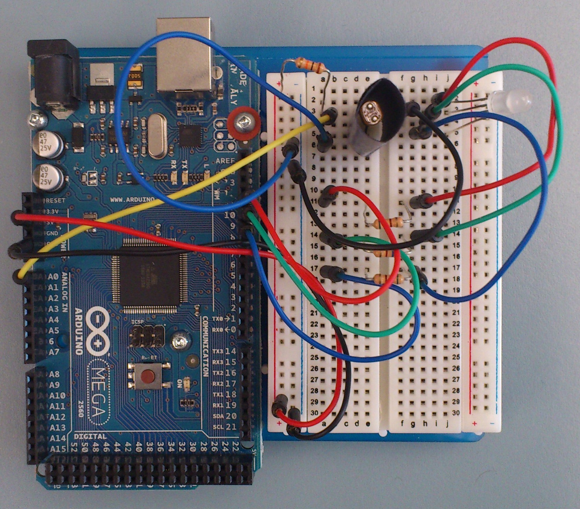 | |
| Arduino Mega | Arduino Uno | Blackness Paper Collar Added | |
| Click the image for total size! | |||
lawmaking/Lab_Color/Lab_Color.ino
/* Color sensor |
|
A RGB LED has three LEDs inside one package. By varying |
the intensity of each LED you tin can mix these primary |
colors and generate a wide range of different hues and |
saturation. |
|
The intensity of a LED is controlled past turning it off and |
on at a variable duty cycle using the analogOutput property |
of the digital output pins. |
|
A photoresistor is a device whose resistance varies with |
the intensity of the light falling on it. Every bit the light |
gets stronger the resistance decreases. Thus you lot tin can measure |
the corporeality of low-cal falling on the photoresistor. |
|
If the illumination on a surface is of a particular colour, |
so the photoresistor can be used to sense how well that |
color is reflected or absorbed by the surface. And thus |
we can observe the color. |
|
*/ |
|
int SensorPin = 0; |
int RedPin = 11; |
int GreenPin = 10; |
int BluePin = ix; |
|
/* The senseColor function sets the LED to a particular |
mix of red, green, and blue, and then senses the intensity |
of the light falling on the photoresistor. The sampleDelay |
parameter is the number of milliseconds to wait after turning |
on the LED before sensing the intensity. Information technology takes a while |
for the photoresistor to react, and so a delay of 1 2d is |
appropriate. |
|
And then that the value returned by this function increases as |
a function of increasing intensity, we subtract the voltage |
read from the sensor from 1024. |
|
NOTE: this part also displays the values read on the |
serial monitor using the printMeasurement procedure. |
|
*/ |
|
int senseColor( |
int redOut, int greenOut, int blueOut, int sampleDelay) |
{ |
int intensity; |
|
// illuminate the surface with iii colors |
|
analogWrite(RedPin, redOut); |
analogWrite(GreenPin, greenOut); |
analogWrite(BluePin, blueOut); |
|
// wait for the sensor to respond |
delay(sampleDelay); |
|
// return the intensity. A lower level means a brighter |
// illumination, so rescale |
|
intensity = 1024 - analogRead(SensorPin); |
|
printMeasurement(redOut, greenOut, blueOut, intensity); |
|
return intensity; |
} |
|
/* The printMeasurement procedure uses the serial monitor |
to print the red, light-green, bluish values prepare for the LED and |
the measured intensity. |
*/ |
|
void printMeasurement(int red, int green, int bluish, |
int intensity) { |
Series.print("RGB LED input values: "); |
Serial.impress(crimson, December); |
Serial.print(", "); |
Serial.print(green, DEC); |
Series.impress(", "); |
Serial.print(blueish, DEC); |
Serial.print(". Intensity: "); |
Serial.println(intensity, DEC); |
} |
|
void setup() { |
pinMode(RedPin, OUTPUT); |
pinMode(GreenPin, OUTPUT); |
pinMode(BluePin, OUTPUT); |
|
Serial.begin(9600); |
} |
|
void loop() { |
int redIn; |
int greenIn; |
int blueIn; |
int blackIn; |
|
int sampleDelay = yard; |
|
redIn = senseColor(255, 0, 0, sampleDelay); |
greenIn = senseColor(0, 255, 0, sampleDelay); |
blueIn = senseColor(0, 0, 255, sampleDelay); |
|
blackIn = senseColor(0, 0, 0, sampleDelay); |
|
Serial.println(" "); |
delay(2000); |
} |
This program currently prints out the values that were passed to the multicoloured LED calorie-free and the resulting intensity that the photoresistor picked upward from existence reflected back from the produced lite on the paper. Past using this basic output recorded in redIn and the other colour intenties, complete the following tasks below.
6.5 Tasks
- Measuring Colour: At present that your circuit is congenital, effort putting different colors of paper above the LED and photoresistor and notice what intensity values are being returned for ruby, light-green and blue for each of the colored papers. You volition notice that it is quite obvious when red and green paper is tested, but blue is harder. This is because the photoresistor is less sensitive to blue parts of the spectrum.
- It is important that the sensor and LED are both pointing upwards toward the same spot.
- How practise the RGB values alter as y'all move the paper to unlike distances from the sensor?
- Compare these to the other students around you lot. Are your numbers close? If they exercise not match, do their ratios to each other at least look similar?
- Colour Recognition: Modify the program to actually recognize red, green, and xanthous colors, and impress out a message describing what color it thinks it is seeing.
- Observe how each paper color will accept unlike values of the three RGB values. This can be used to place the color.
- Note the blackness levels. This gives you some thought of how much light from the surroundings is reaching the sensor. This is noise and can be subtracted from the red, green and bluish readings to show how much red, light-green and blue is actually being sensed past the photoresistor.
- Yous might need to use the absolute value part,
abs(x), which returns the magnitude of its argument. This is useful for checking if two values are close to each other. For example,if ( abs(red-green) < xx )tin can be used to test if the red and green values are roughly the same. The twenty is the range of error that determines what level of precision yous desire for the readings. As well high of a range tin can result in the incorrect colour beingness identified and too low of a range can result in no colour beingness identified.
- Calibration: We don't ever conduct the experiment in the exact aforementioned environs all the time. Typically in experiments we have some sort of reference value of what kind of values nosotros're suppose to get. For this part you're going to add together a pushbutton and when it'south pressed, information technology will permit the program to enter a calibration manner. In this style each colour piece of paper will be held up to the sensor and their ruby, green, blue and black levels will be saved as that coloured paper's reference values. Then when trying to recognize the colour, you can compare the readings of the coloured paper to each coloured paper's referenced values and if they are close enough within a certain mistake, the program volition identify it as that colour.
- Use impress statements! You can use this to indicate when you've entered calibration manner and other important information such as which colour is currently being calibrated, when to switch to the next colour, what the recorded reference values are, and and then on. Print out whatever data y'all believe is important.
- Use
delay()statements to allow time to switch between unlike sheets of paper.
Source: https://sites.ualberta.ca/~jhoover/ArduinoIntro/section/lab_Color.htm#:~:text=When%20the%20illumination%20on%20a,the%20color%20of%20the%20surface.
Posted by: brooksbuslow.blogspot.com
0 Response to "Can You Use A Photoresistor To Sense Color?"
Post a Comment